
The water hammer
The term water hammer is commonly used as a synonymous of unsteady flow, suggesting noise and fast changing pressure variations sometimes related to devastating effects on the system.
Pipelines, both for water and sewage, are vital for our modern civilization and their safety and protection should be one of the top priorities. During the studying and assessment of the pipeline network their behaviour under transient conditions will reveal the potential for damages. This involves numerical simulations carried out to reproduce events, planned or accidental, with consequences on the system.
The main causes of transients are :
-sudden changes in demand
-pump start up
-pump failure
-rapid closing and opening of isolation devices
-rapid filling of pipe line and fire fighting installations
-opening and closing fire hydrants
-pipe flushing and draining operations
-feed tanks draining
Water hammer can also be described as a propagation of energy, as in the transmission of sound, and from basic physics as a wave motion the energy is associated with the elastic deformation of the medium.
The celerity of sound waves a in rigid pipes is given by a=[K/ρ/(1+K*D/E*e)]1/2
Where E is the modulus of elasticity;
D is the pipe diameter;
e is the wall thickness;
K is the bulk modulus;
ρ is the density of the fluid medium.
Pump failure
One of the most critical occurrence in water and wastewater system is the pump failure also called pump trip. This definition means actually a full blackout, interrupting the pump’s head and causing a deceleration with consequent negative pressure variation propagating with a speed whose value depends on the fluid and pipe properties. Negative pressure is always a problem for possible pipe deformation, collapse, gaskets movements and entrance of contaminated water and pollution through points of leakage. If the hydraulic grade line, during the pump failure, drops to a negative value corresponding to the vapour pressure there is the risk of column separation, generated by the formation and collapse of vapour pockets producing serious and unexpected high frequency rises in pressure, sometimes fatal for the system.
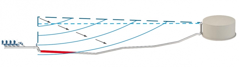
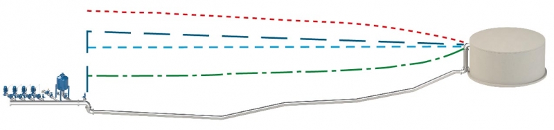
The plot above shows a pipeline profile, with pumps and downstream tank as boundary conditions, where the dark blue dotted line represents the HGL and the light blue dotted line is the static. The picture represents the negative pressure wave propagating downstream as an effect of pump failure, where the red segment depicts the area exposed to negative during the initial phase of the event.
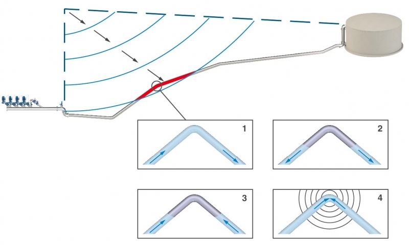
The plot above shows the negative pressure wave propagating downstream, as an effect of pump failure. The red segment depicts the area exposed to severe negative pressure. The change in slope represents a location at risk of column separation, caused by vapour pockets forming and then collapsing creating unwanted water hammer as explained on the 4 pictures.
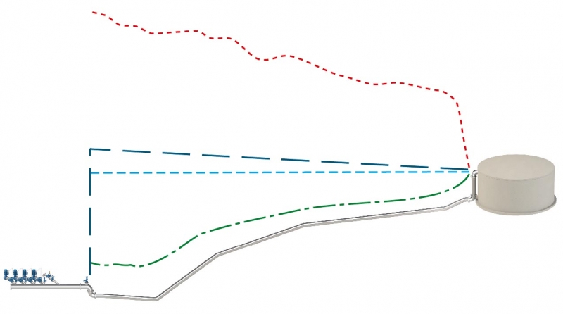
The results of pump failure can be summarized in a plot showing the envelope of the maximum and minimum pressure values reached during the simulation, in the picture above shown respectively in green and red. It is evident how the system reaches a full vacuum on the entire profile and an extreme rise in pressure due to the column separation, occurred at the change in slope.
Water hammer prevention
In order to prevent transients and unwanted damages on the pipeline systems we basically have to reduce the variations in velocity of the fluid and, when this happens, try to proceed as slow as possible.
It will therefore be mandatory to:
- operate slowly during valve operations, especially on the final position of the device.
- control the pipe filling through the use of anti-surge combination air valves, example the CSA RFP models.
- introduce air or water into the pipeline, at those locations where negative pressure conditions are likely to occur.
- adopt controlled pump start up procedures to avoid rapid changes in flow.
- carry out detailed computer analysis to evaluate and assess the risk associated to the system and transient events.
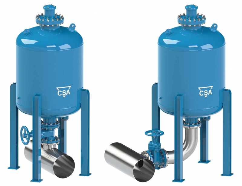
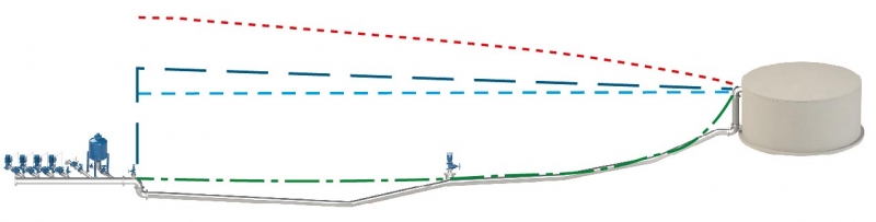
One of the best and most reliable solutions to the problem, and working as a standalone or in combination with other devices like anti-shock air valves and pressure relief valves, is the CSA air vented anti surge tank also called A.V.A.S.T.
This type of anti surge device can be installed in derivation from the main line or directly on top of it, and simply provided with an isolation device to allow for maintenance. No additional check valves, by pass or restrictions are needed. Compared to other solutions A.V.A.S.T. doesn’t need any kind of compressor, bladder or external source of energy. This means a reduced maintenance, higher reliability and, more important, a lower volume is needed to provide the same degree of protection, in comparison with bladder tanks or air vessels.
The plot above shows the pressure envelope of the transient event caused by pump failure on a pipeline with A.V.A.S.T. installed as a protection. The red and green are the maximum and minimum pressure values reached during the simulation, it is clearly visible the beneficial effect in terms of negative pressure and consequently reduction of water hammer.
The plot above shows the pressure envelope of the transient event caused by pump failure on a pipeline with A.V.A.S.T. installed as a protection, in combination with anti-shock air valves (CSA AS series). In this case the effect of the air valve will help reducing the volume of A.V.A.S.T., containing budget and design requirements. The red and green are respectively the maximum and minimum pressure values reached during the simulation. Depending on the fluid A.V.A.S.T. can be placed at the pumping station or along the profile and calculated to perform with air valves and pressure relief valves, CSA VRCA series, if required.
Water hammer analysis
Simulation - pipeline 1 - pressure profile without any protections
Example of a transient event generated by a pump trip, at first we notice a drop in pressure followed by a surge as the water column moves back towards the check valves of the pumping station.
Simulation - pipeline 1 - pressure profile with CSA anti-water hammer devices
Example of a transient event generated by a pump trip in presence of CSA surge anticipating valve XLC 321/421 and anti hammer air valves FOX 3F AS range. The effect of the valve with anticipated opening is evident in preventing unwanted increase in pressure with possible damages to the system.
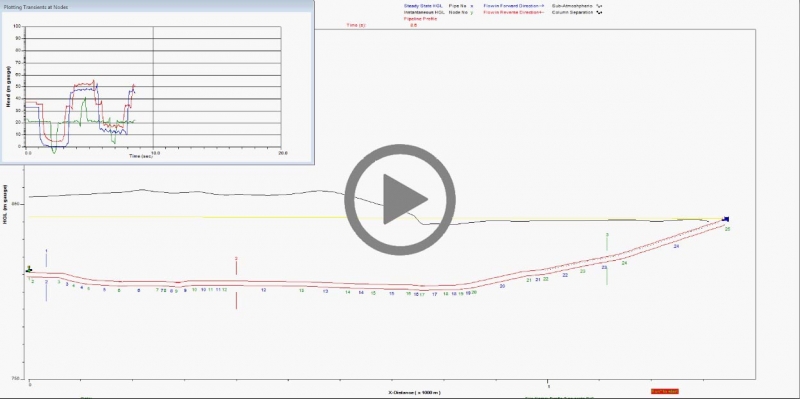
Simulation - pipeline 2 - pressure profile without any protections
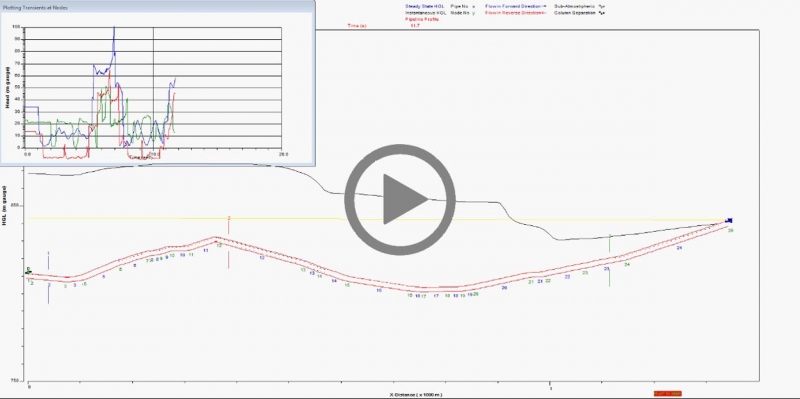
Example of a transient event, generated by a pump trip, leading to column separation with vapor pockets formation and collapse. This phenomenon is associated to severe and sudden high frequency changes in pressure.
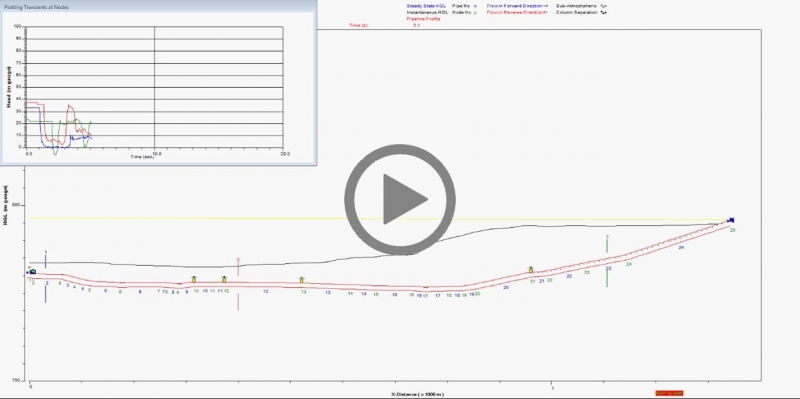
Simulation - pipeline 2 - pressure profile with CSA anti-water hammer devices
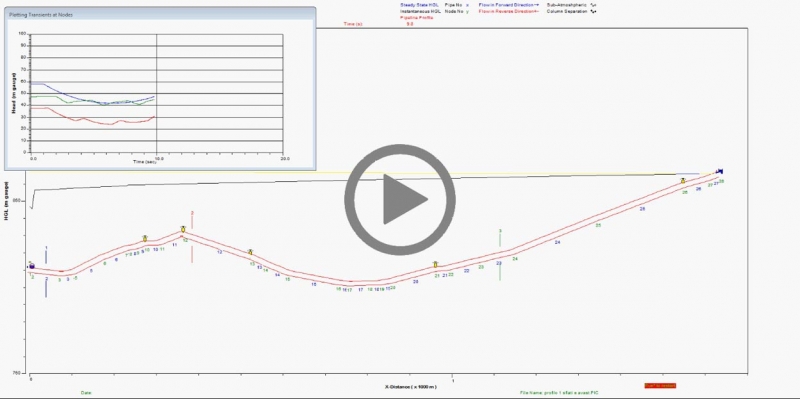
Example of a transient event generated by a pump trip in presence of CSA surge vessel AVAST (patent pending) and anti hammer air valves FOX 3F AS range. The effect of the AVAST pushing water back into the system, following a pump trip, is evident to contain the drop of the hydraulic grade line and prevent negative pressure conditions.